When a motor drive goes down, production often grinds to a halt. How do you find and resolve the problem quickly?
Thank you for purchasing LS Variable Frequency Drives! SAFETY INSTRUCTIONS To prevent injury and property damage, follow these. The meaning of each symbol in this manual and on your equipment is as follows. RMS Symmetrical Amperes for iS5 series. Model Rating SV008iS5-2, SV008iS5-4, SV015iS5-2, SV015iS5-4, SV022iS5-2, SV022iS5-4. Pub # 890046-10-00 Dec. 2015 SG Series Variable Frequency Drive Service Manual. Thank you for purchasing LS Variable Frequency Drives! SAFETY INSTRUCTIONS Always follow safety instructions to prevent accidents and potential hazards from occurring. In this manual, safety messages are classified as follows: WARNING CAUTION Throughout this manual we use the following two illustrati ons to make you aware of safety. Thank you for purchasing LS Variable Frequency Drives! Safety instructions are prepared to use the product safely and correctly by preventing any accident or risk beforehand, so they should be always kept. Z In this manual, safety instructions are divided into two classes; each has the following meaning.

When that variable frequency drive (VFD) goes down, you're under pressure to get it back online. Don't let this pressure make you take even longer to resolve the problem. Instead, remember the VFD troubleshooting checkpoints: check the basics (the controller display, connections, and temperatures), check the motor, and check the drive - then check a little closer.
Check the controller display. Most VFD controllers include an interface to set up the drive for operation and to display information about its operation, once it's underway. Although the information displayed varies, most controllers tell you about high current (usually including blown fuses and overload trips), high and low voltages on the input and output sides, high temperatures, internal faults, and even offer advanced power diagnostics.


Check the connections. If the fault codes can't help you track down the problem, then check the connections. Loose connections are among the most common causes of faulty operation in VFD applications. Just eyeballing a connection is sometimes enough to know it's loose. You can also check for a voltage drop across the connection if you're still powered up - or resistance through a connection if you're powered down. Don't forget to isolate the connection to get a reliable reading.
Check temperatures. Checking the temperature of connections with a temperature probe or IR-thermometer is one way to tell if they're loose. They should never be hotter than the connecting wires. You can check temperatures in the drive and at the motor. For example, if the motor insulation is unsuitable for VFDs, it'll gradually degrade until it develops a short. Such shorts are often too small to blow a fuse, and too intermittent to trip an overload - but enough to shut down a controller. An IR thermometer can show what's going on. Also, use your nose: If a motor smells hot, it is.
You can do more. But usually, just checking the basics will be enough to uncover any problems you may have and get the system running again. That can give you the time you need for a permanent fix.
Sidebar: Check a Little Closer
In new installations, apparent problems with drive performance are often due to improper application, drive selection, setup, or installation of the motor as well as the drive. Sometimes 'drive problems' are due to process control logic and not the drive at all.

In the case of frequent breaker trips, you may need to examine protection coordination, to ensure your breakers are the right size from the drive back to the service. You may also need to check other branch and feeder circuits. But first, see if your drive can reduce inrush current with a 'soft start' function. Also, you may need to check:
Variable Frequency Drive Used
- Current to the motor (ammeter),
- Voltage notching (oscilloscope),
- Inductive noise in signal, control, or power wiring (oscilloscope),
- Cable routing (visual inspection),
- Damaged signal, control, or power wiring (insulation resistance, TDR), and
- Current through the controller during sudden load changes, or during speed ramps (controller display).
Sub Menu
| Home |
| Products Industrial Automation Motor Controls |
| Online Store |
| Training |
| Download |
| Site Map |
| Industries & Application |
| Contact Us |
IS5
Sensorless & sensored vector control inverter
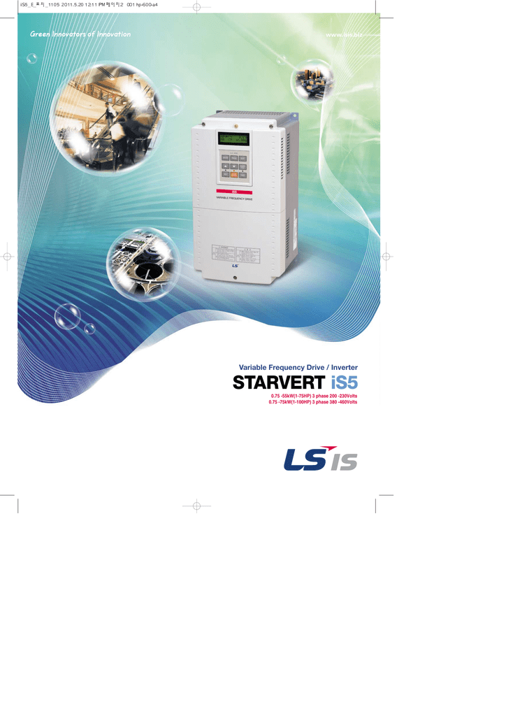
Sensorless & sensored vector controller iS5 (0.75~75kW) keeps your application in more stable, durable and precise condition. And iS5 maximizes user-convenience with Auto Tuning, PID control, etc.
Features
- kW/Voltage Ratings: o 0.75 ~ 55kW, 3 phase, 200 ~ 230VAC o 0.75 ~ 75kW, 3 phase, 380 ~ 480VAC - Selectable V/f, Sensorless vector, Sensored vector control (Optional) - Built-in process PID control - Optimum acceleration & deceleration for a maximum torque - APP parameter group for special operations; Traverse, Multi Motor Control, DRAW - Multi-function I/O terminal: Input: 27 functions / Output: 21 functions - Multi Motor Control (Up to 4 motors: Optional) - Motor parameter Auto-tuning - Parameter Read/Write function using a detachable LCD Keypad - 8 Preset speedsl - Extension I/O boards (Optional) : Sub-A, Sub-B,l Sub-C - Communication options: Modbus RTU, Profibus-DP, DeviceNet, RS485(LS Bus), Fnet(LS PLC link) - Built-in Dynamic braking transistor (Up to 7.5kW [10HP]) - Monitoring & commissioning PC based software tool (Drive View)
Ls Is5 Variable Frequency Drive Manual Pdf
Type